Many of us have had the pleasure of witnessing the rapid evolution of O&P through the years, but despite the technological advances, many aspects of the field are still grounded in traditional fundamental elements. Some of these tools, principles, and habits have been passed down through generations.
We learned to fabricate metal orthoses by taking measurements and using specific anatomical landmarks with the patient lying down and tracing the leg over paper. This is a fascinating technique for creating a three-dimensional device that transfers the outline of the leg to the reverse side to make the contour of the uprights, bands, stirrup, and the location of the mechanical axis of the ankle joint. One of the landmarks used as a reference for the anatomical joint was the apex of the medial malleolus. But why the medial malleolus? In 2015, I was asked this question while visiting Fior & Gentz, a company in Germany that developed a novel orthotic component, and attending a presentation as the orthotics instructor in the master’s program in prosthetics and orthotics at the University of Pittsburgh. I repeated that the medial malleolus was the landmark for the ankle’s anatomical joint, but my answer was based on a habit acquired over the years, and lacked solid scientific evidence. I didn’t know why exactly. Fabricating a metal AFO or KAFO requires strict adherence to protocols and steps to ensure the closest anatomical fitting. The primary goal was to design a device that is as aligned as closely as possible with the three planes—a significant challenge, considering the only elements available were a trace and measurements without a model.
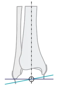
It was then that I learned about a study done at UCLA’s biomechanics laboratory in 1969, where Isman and Inman used 46 cadaver legs to determine the precise location of the rotation axes for the talocrural and subtalar joints.1 They found that the talocrural axis, when viewed in the frontal plane, intersects the longitudinal axis of the tibia at the same level as the distal end of the fibula. The correct landmark for the anatomical axis of the ankle was the distal end of the lateral malleolus. Two additional studies confirmed these findings, as reported by Lundberg et al. and Shimotori et al. (Figure 1).2,3 I was stepping away from what I considered to be second nature from my experience, and it made me question what other experience-based habits are carried out during regular practice and with new technologies.
The Shift to Plastic
The shift to plastic AFOs and KAFOs in O&P facilities across the country is well known. I am not implying that metal orthoses no longer exist—many patients are still accustomed to them, and we continue to manufacture them in small quantities. A truly master-craft fabrication process combines hand skills, attention to detail, and protocol measurements to secure the closest alignment possible—from a static lying down position to standing up and walking. Additional accessories were necessary to correct ankle deviations in the coronal plane like kneecaps and T-straps at the sagittal and frontal planes.
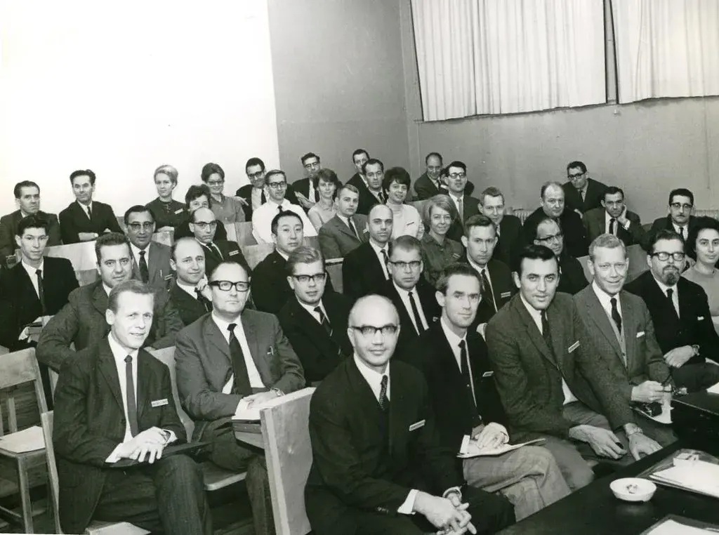
The transition from heavy metal and leather orthoses attached to shoes to thermoforming materials occurred in the late 1960s. With the introduction of new materials and techniques, new protocols were also established. Casting procedures, fabrication techniques, and fitting protocols evolved as we became familiar with this new material. Hybrid combinations of metal components and plastic were part of this constantly evolving transitional period. And here we are, almost 60 years later, still using the same thermoforming material, along with an array of designs and information related to the casting technique, trim lines, and new thermoforming materials. According to the 2022 ABC Practice Analysis of Certified Practitioners, 78 percent of custom AFOs are thermoplastic and 14 percent are carbon fiber.
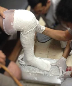
The fundamental casting procedure for a plastic AFO is the same. The patient is positioned in a seated posture to maintain the foot and ankle complex at a 90-degree angle in the sagittal plane, which is considered the neutral position. Subtalar correction is applied manually in the frontal plane, marking bony prominences and below the fibula head. Hundreds of casts are taken every day, even with the foot flat on the ground, following this basic technique. The entire casting procedure can be completed in 15 minutes.
Nevertheless, the patient remains seated and still. Despite this meticulous process to capture the best alignment with this measuring technique designed for metal orthoses, have you experienced the sensation of missing something? In our rush to adopt new materials to replace the stigma of a device that was seen as outdated, did we develop new processes? We are all familiar with the vicious circle of achieving a perfect cast at 90 degrees at the ankle joint and fabricating a thermoformed orthosis only to notice that the patient is uncomfortable and fighting for space at every step. We ultimately create the space for the navicular or malleolus with a heat gun, adding pads, and corrective straps. The lack of stiffness to tolerate rotational, repetitive, and loading forces that restrict the ankle motion creates bigger issues for both the user and the device itself.
Heavy devices, complex repairs, and shoe problems were just a few of the issues associated with these orthoses, not to mention patient complications such as muscle atrophy, calluses, skin breakdown, fungus, and other related issues. But how much difference was there after switching to plastic? The weight and material tolerance were evident, and the cosmetic appeal was a big plus, but many of the same issues remained: skin breakdown, calluses, and repairs that required a new device. We all have a patient who breaks everything, which presents a challenge for the practice and the clinician’s reputation. For metal orthoses, our component selection was based on the material properties of the uprights, which were either aluminum or steel, as well as the width and thickness of the uprights. After several broken bars, we used to request thicker and heavier bars from the manufacturers so we could fix the problem.
With the thermoformed materials, thicker plastic with reinforced carbon or corrugations was the alternative. Hybrid designs with metal componentry and carbon fiber laminated designs were also an option. The dynamic alignment was practically nonexistent or not considered due to the limitations of the orthotic components and designs. The conclusion was clear: Regardless of whether metal or plastic devices were used, we were imposing static and rigid designs with standard components that blocked the body’s ability to respond to dynamic motion in three planes. Something else was needed, and it was not only material or components. We needed to match as closely as possible the proper alignment, components, and orthotic design of each individual under actual use conditions, which involve gait rather than static positions.
A New Orthotic Approach
While advanced prosthetic technology for the upper and lower limbs has been introduced frequently over the years, orthotic technology has been neglected and relegated to a few materials or the introduction of prefabricated carbon fiber designs. The rapid pace of 3D-printing technology is transforming how traditional designs, previously created using thermoforming materials, are produced. Quick digital modifications facilitate this process, but we need to address the issue at hand: There should be a correlation between the mechanical properties of the materials and components used and the dynamic requirements of support and resistance for each patient during ambulation.
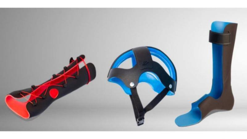
My visit to Fior & Gentz opened my eyes to the importance of breaking away from traditional habits like blocking the plantarflexion and universal neutral alignment on every design. The introduction of new calculated components with the ideal resistance/assistance forces to treat each muscle group responsible for the ankle motion based on the patient’s needs is transforming how we treat the populations affected by neurological conditions. Fior & Gentz was the pioneer in Europe, introducing the Neuro Swing ankle joint system in 2011, which was launched in the United States in 2015. Becker Orthopedic launched the Triple Action ankle joint in 2016, and Ottobock introduced the Nexgear Tango ankle joint in 2019 with an updated version released in 2025.
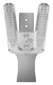
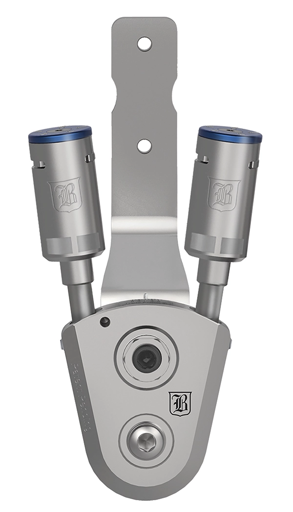
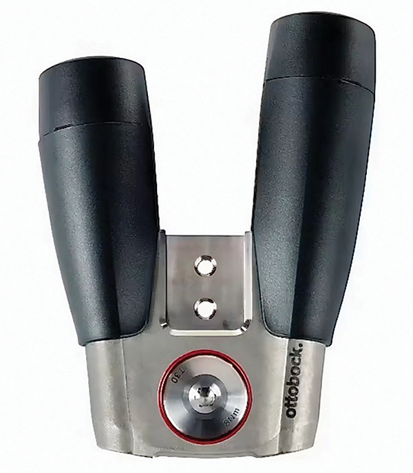
Photographs courtesy of Fior & Gentz; Becker Orthopedic; Ottobock.
These adjustable customized ankle joint designs aim to establish a correlation between the pathological needs of the patient with the assistive and resistive mechanical forces to improve gait and balance. Each one offers features not previously existent, such as interchangeable resistance forces, range of motion control, and independent alignment—all of which are achieved without interfering with one another.
The unique features of these ankle joints finally offer practitioners the possibility of achieving a dynamic and responsive alignment with components that can tolerate high loading forces.
Applying the traditional casting method developed in the late 1960s for thermoforming materials does not apply to these new mechanical elements and orthotic principles. Static and restrictive designs do not blend with this new kind of componentry.
Gait-Related Posture
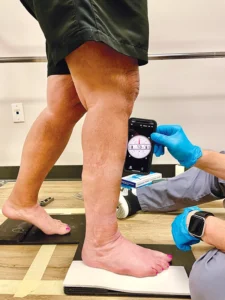
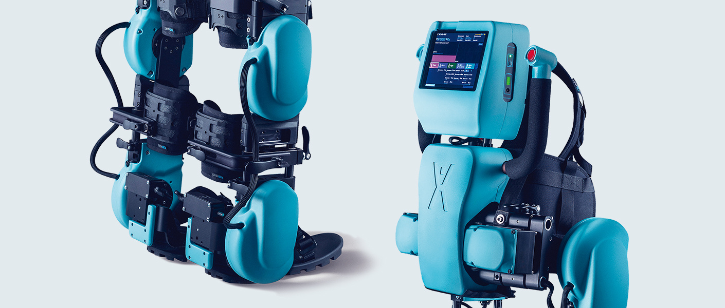
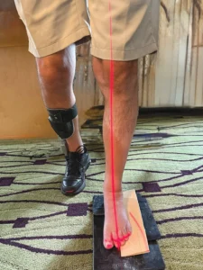
In 2015, Fior & Gentz introduced the concept of gait-related posture with an operator device and sensors to detect the spatial position of the knee and foot in the sagittal and frontal planes to capture the ideal natural posture during the gait cycle. The correct use of a laser beam or a plumb bob can also help to reach the ideal posture in the sagittal and frontal planes. Finding the ideal posture during gait represents a challenge to anyone affected by a neurological condition. The evident weakness of the muscle groups and lack of balance makes this a very complex task.
To address the mechanical needs of a specific neuromusculoskeletal condition we must understand the complex three-dimensional interactions of the human body during gait.4 During the early stance phase, the lower limb must be supple to absorb shock and accommodate terrain discrepancies. In contrast, the latter portion of the stance phase requires that the same structures become rigid so they can withstand the acceleration forces associated with propulsion.5
These new adjustable customized ankle joints can generate enough control to dampen the force after initial contact, allowing passive plantarflexion, and sufficient stiffness to support the body at midstance and generate propulsion at terminal stance.6-7 Therefore, the casting must be done while addressing the ankle, knee, and the hip during the period of the gait when the body is on a single limb, without acceleration, and the ground reaction forces are controlling the knee and keeping the hip stable.8 The midstance period begins at full forefoot load and ends at heel lift. When walking, it is the most extended period, occupying 40 percent of the stance phase. The center of mass is at the highest point, and the entire lower limb pivots up and over the talus. Normal gait requires stability in the stance phase, a means of progression, and energy conservation. Stability requires constant balancing of the trunk over the base of support. During progression, potential energy is converted into kinetic energy. Much of the kinetic energy for swinging the limb is provided by inertia, which is augmented by the plantar flexors (85 percent) and hip flexors (15 percent).9
Midstance Casting and Planes of Motion
The mechanical function, despite the design of any of the adjustable customized ankle joints, is relevant to the sagittal plane. As related to the foot and ankle, dorsiflexion/plantarflexion occurs at the sagittal plane, inversion/eversion occurs in the frontal plane, and adduction/abduction occurs in the transverse plane. The triplanar movements of the ankle, subtalar, and foot joints produce supination and pronation. Capturing the ideal posture of a patient affected by a neurological condition in this specific position poses a significant challenge.
The Sagittal Plane
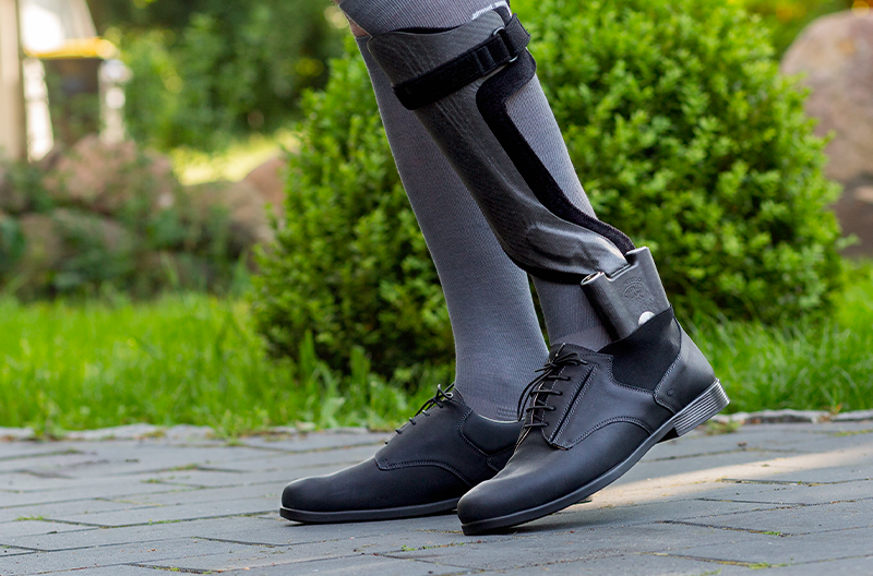
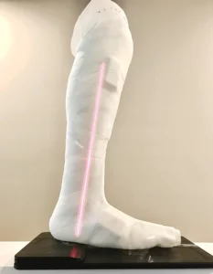
At midstance, the tibia is inclined by 10-12 degrees according to Owen et al. This is also known as the shank vertical angle. The tibia inclination stabilizes the knee, hip, and trunk. At this plane, the shoe is an important external biomechanical element, so it is imperative to include the correct shoe pitch.10 The difference between the heel height of the shoe and the anterior sole thickness determines the height of the casting plate and the proper fit of the orthoses in the shoe. A cast with a flat foot section obtained over the floor is unacceptable and creates issues during the dynamic alignment and fit in the shoe.
At the sagittal plane, the practitioner can set up the initial bench alignment with the shoe and perform the static and dynamic alignment with the patient. Numerous studies have shown that the calculated resistance and stiffness of the ankle joint can positively impact knee and hip extension during gait. This work can’t be done by the ankle joint itself, regardless of the amount of hysteresis, particularly in the mechanical properties of precompressed disk springs found in the Neuro Swing ankle joint, compared to coil springs. The AFO fabrication plays a fundamental role in the proper functioning of the adjustable customized ankle joint. The carbon fiber, in conjunction with the anterior shell design and the correct toe spring angle and stiffness, works in harmony with the mechanical properties of the powerful springs. The mechanical axis must be located at the distal lateral malleolus and at the center of the ankle in the two equal parts.
The Frontal Plane
After reviewing and participating in the fabrication of over a thousand Neuro Swing AFOs, I can affirm that the frontal plane is the most critical aspect of the casting procedure. Here, the correct alignment ensures the proper mechanical function of the ankle joint and its durability. Adopting the traditional casting method in a seated position without the correct alignment reference in weight bearing at midstance can result in fracturing the stirrup due to the decisive moment of force created by unbalanced forces. The accurate alignment and gait posture are reflected during midstance and terminal stance through the center of mass and ground reaction forces.
The importance of subtalar joint correction plays a significant role in the proper function of adjustable customized ankle joints. The subtalar joint dissipates torsion between the rear foot and the leg. Even though some of its motion is dissipated, the pronation of the subtalar joint continues to convert frontal plane motion into tibial rotation.
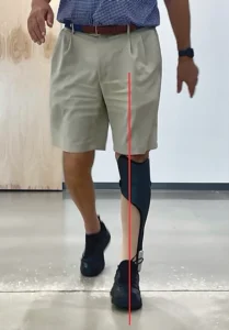
The combination of a low arch and an anteverted hip results in excessive internal rotation of the entire leg, significantly increasing valgus collapse at the knee. This misalignment must be addressed before casting by applying corrective manipulation to capture the ideal alignment. The patient is positioned between parallel bars and adopts a midstance position, with a laser beam guiding reference point marks over the knee and forefoot. The base of support should be narrow and no more than 4 inches.
Incongruency between the mechanical axis of the adjustable customized ankle joint and the anatomical axis of the talocrural joint generates unnecessary vertical motion of the orthosis on the leg and friction. This axis must be parallel to the floor. The use of a valgus wedge from the lateral border of the heel to the forefoot during casting provides excellent biomechanical support for patients with excessive supination and lateral deviation.
The Transverse Plane
Following the line of progression, the mechanical axis is perpendicular to the transverse plane. The foot progression angle average is 7 degrees of external rotation. Patients with an angle larger than 10 degrees represent a challenge to the proper function of the mechanical joint due to the torsional forces. The carbon fiber construction of the orthosis must be solid and stiff enough to prevent any torsional movement. The proper angle of the mechanical joint in relation to the line of progression facilitates the tibia progression and the appropriate release of impulse forces generated by the springs from midstance to terminal stance. Manual positioning of this angle is crucial during the casting process.
Recommendations
The aforementioned statements underscore the significance of a long-needed transition in the orthotics field. Regardless of the preference for the manufacturers of these designs, the mechanical principles and function remain the same. After dedicating the past nine years to raising awareness about this technology, I have also witnessed the constant changes and improvements in each design resulting from continuous learning and evolution. The casting procedure, considering the gait-related posture initiated by Fior & Gentz, is also part of this evolution, and as practitioners, we will continue adding elements to facilitate this labor. As usual, the amount of effort and dedication to develop and apply this technology is not reflected in the reimbursement due to lack of a specific code. As a result, despite scientific evidence in numerous publications, these orthoses remain out of reach for many patients who could benefit.
Santiago J. Muñoz, CPO, FAAOP, president, Equation Orthotic Technologies, is a former faculty member at the University of Pittsburgh and former clinical education specialist, Fior & Gentz. He has over 30 years of experience in patient care and education. He can be contacted at santiago@equationortech.com.
References
- Isman, R. E., and V. T. Inman. 1969. Anthropometric studies of the human foot and ankle. Bulletin of Prosthetics Research. https://www.rehab.research.va.gov/jour/69/6/1/97.pdf
- Lundberg, A. 1989. The Axis of Rotation of the Ankle Joint. Karolinska Hospital, Stockholm and Lund University, Sweden.
- Shimotori, D., et al. 2015. Measurement of the rotation axis of the ankle in vivo. Presentation during the IPSO France.
- Michaud, T. C. 2011. Human locomotion. Newton, Massachusetts: Newton Biomechanics.
- Perry, J. 1992. Gait Analysis: Normal and Pathological Function. Thorofare, NJ: Slack.
- Kerkum, Y. L., W. Philippart, and H. Houdijk. 2021. The effects of footplate stiffness on push-off power when walking with posterior leaf spring ankle-foot orthoses. Clinical Biomechanics 88:105422.
- Kerkum, Y. L., M-A. Brehm, A. I. Buizer, J. C. van den Noort, J. G. Becher, and J. Harlaar. 2014. Defining the mechanical properties of a spring-hinged ankle foot orthosis to assess its potential use in children with spastic cerebral palsy. Journal of Applied Biomechanics 30(6):728–31.
- Kerkum, Y. L., J. Harlaar, A. I. Buizer, J. C. van den Noort, J. G. Becher, and M-A. Brehm. 2013. Optimising ankle foot orthoses for children with cerebral palsy walking with excessive knee flexion to improve their mobility and participation; protocol of the AFO-CP study. BMC Pediatrics 13:17.
- Jagadamma, K. C., E. Owen, and F. J. Coutts, et. al. 2010. The effects of tuning an ankle-foot orthosis footwear combination on kinematics and kinetics of the knee joint of an adult with hemiplegia. Prosthetics and Orthotics International 34(3):270–6.
- Owen, E. 2010. The importance of being earnest about shank and thigh kinematics especially when using ankle-foot orthoses. Prosthetics and Orthotics International 34(3):254-69.


.jpeg)

-1.png "Gaza Fund (1)-1")